Waterline Control Centre Wiring Diagram

Vt Commodore Ignition Wiring Diagram, Complete Wiring Diagrams For Holden Commodore VT, VX, VY, VZ, VE, VF, 5.36 MB, 03:54, 32,796, John Amahle, 2018-08-01T19:37:41.000000Z, 19, Vt Commodore Ignition Wiring Diagram, to-ja-to-ty-to-my-to-nasz-swiat.blogspot.com, 1272 x 1800, jpeg, bcm pcm 12j swiat nasz, 20, vt-commodore-ignition-wiring-diagram, Anime Arts
[0m:23s] these videos will focus specifically on wiring diagrams that are related to industrial control and what you might encounter when laying out schematics for a control panel that include power and signal drawings. [0m:39s] in this brief series, we will cover things such as what a wiring diagram is and how Wiring centre description 2. * power relays (as required) the replaceable parts are:
All wiring must conform to local/ national building standards and electrical codes. Use this control centre only as described in this manual. Manifold and actuators 4. Besides a single line and wiring diagram, practically every piece of mentioned electrical equipment will be presented in the switchboard’s interior drawing, i. e. In open cubicle’s door view. The wiring diagram and physical layout of the equipment inside the motor control centre. A front view with a closed door will also be given, so in that. The centralized wiring diagram holder should be located on the inside of a bottom wireway cover, in any convenient section. Determine which section you want to locate the centralized wiring diagram holder.
WLC5000 - Fill W/High and Low Alarm

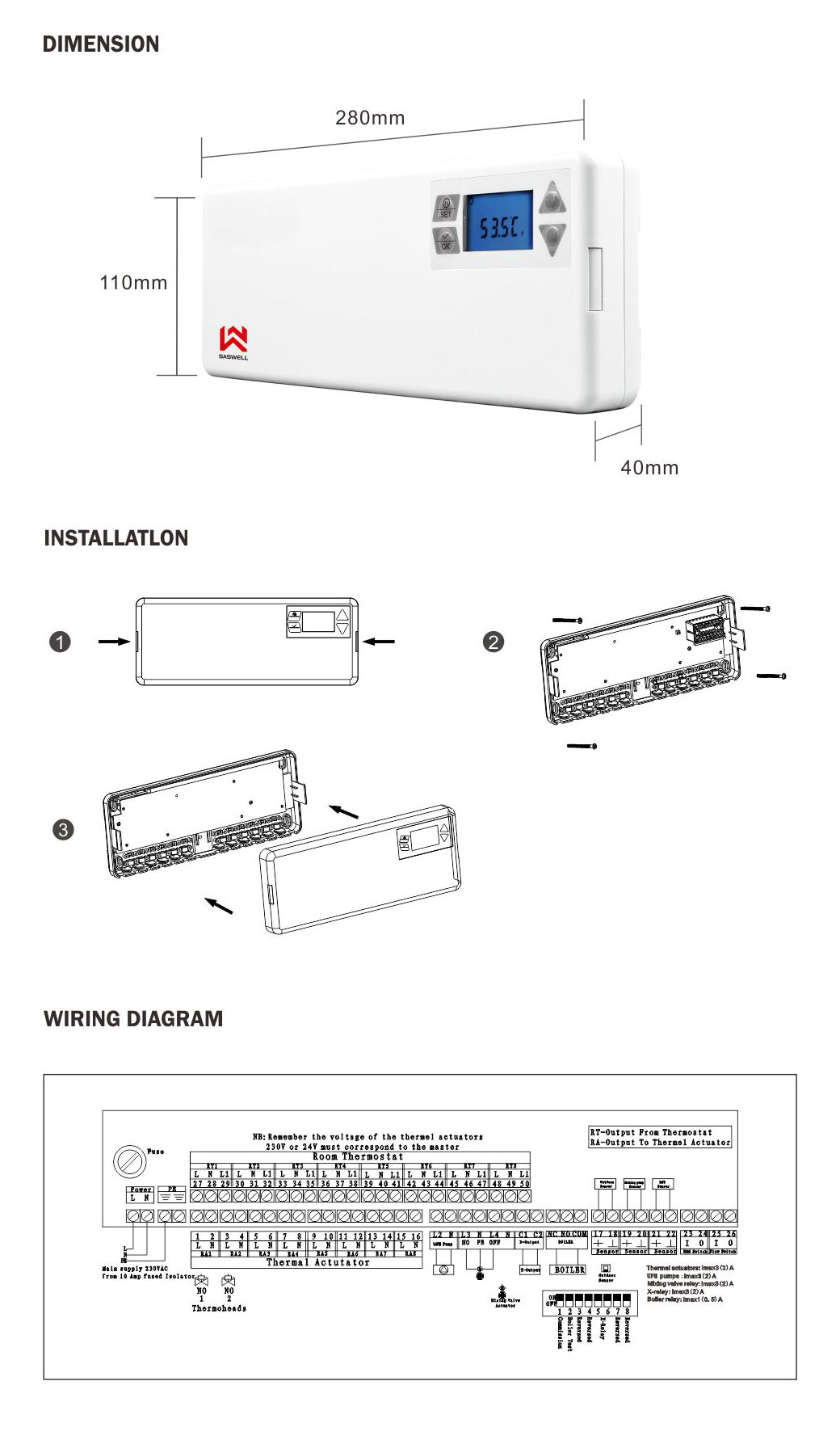
Waterline Heating Control Center SCU209I manufacturer,China Waterline Heating Control Center SCU209I

Wiring boiler in control centre | DIYnot Forums
Installer’s guide to UFH Wiring - Ambiente
Automatic Water Level Controller Wiring Diagram For 3 phase - Electricalonline4u

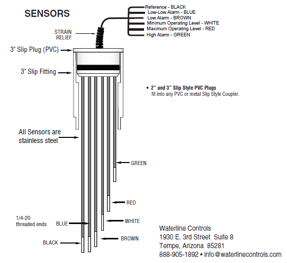
WLC Nina™ PVC Type Liquid Level Sensor Switch - Waterline Controls™

Dpdt Center, Toggle Switch Wiring Professional How To Wire Intermatic Control Centers With Parts

Roadtrek Modifications/ Mods, Upgrades, and Gadgets.: Automatic RV Hot Water Recirculation System

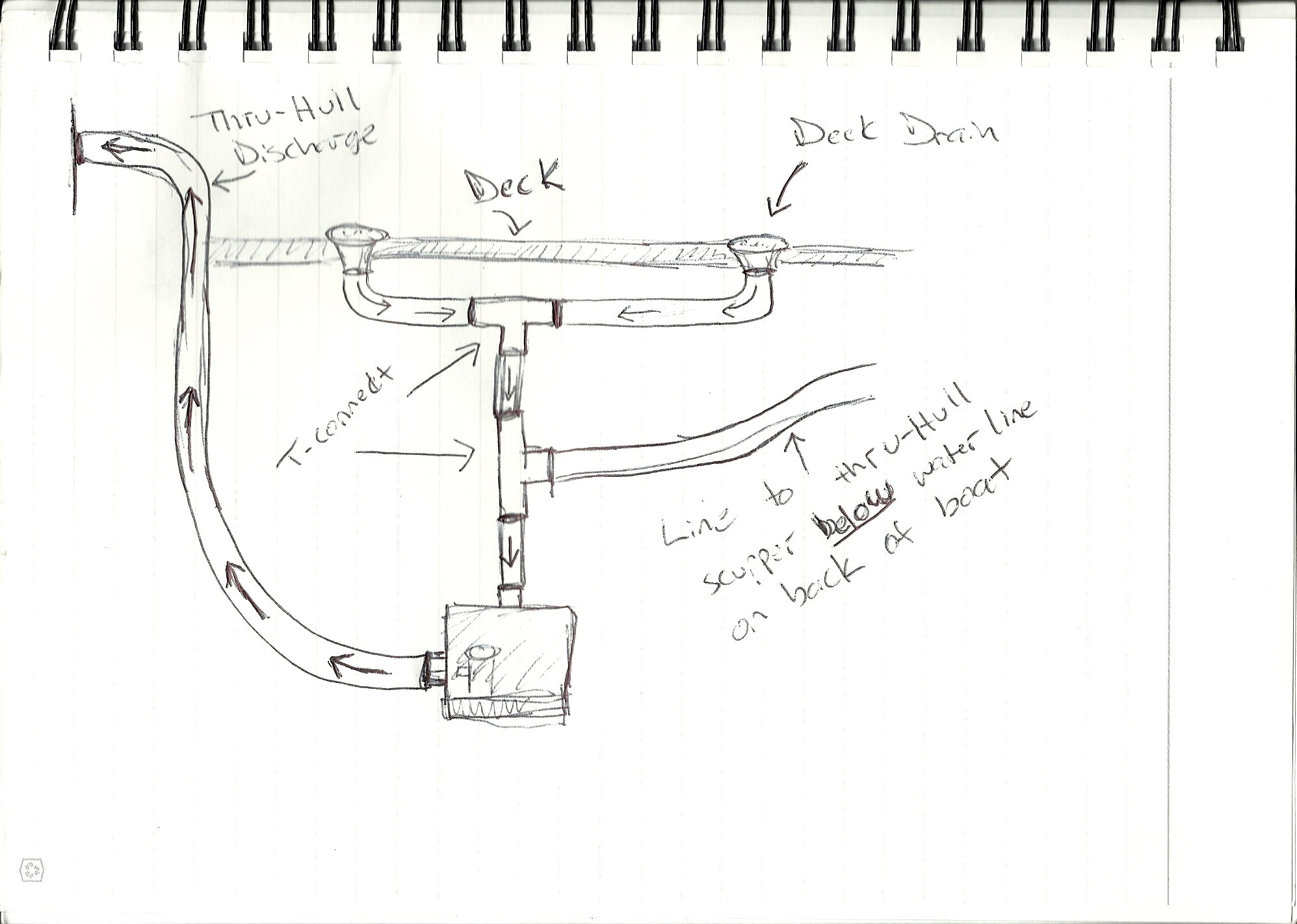
Livewell Drain Below Waterline - Best Drain Photos Primagem.Org

Square D Mcc Bucket Wiring Diagram Gallery
